The RSO / MFCO Operator Interface to the Flight Termination System
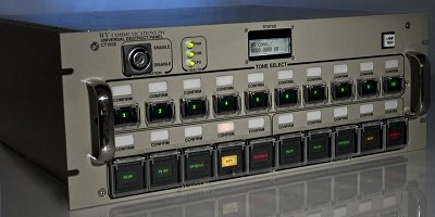
The Flight Termination Panel (FTP), also known as the RSO or MFCO panel, is the user interface to the Flight Termination System. It accepts command requests via buttons or remote interface, acknowledging them by LEDs and providing verification information via separate LEDs, traceable to the CVR in the transmitter chain. WV has a variety of FTP configurations available, from rack-mounted units to desktop units, and from single to multiple vehicle panels, as well as units with either fixed button nomenclatures or programmable LCD color display pushbuttons.
Switch Options
FTPs can be supplied with either toggle switches or pushbuttons. With pushbuttons, the button illuminates to show the logical state of the command and can be logically programmed in the FCP for a variety of actions, such as momentary, push lock / push release, or interlock. If toggle switches are used, they must be logically programmed as momentary and will physically hold the desired state. This provides less versatility of action, but can be compatible with the rest of the system.
From the FTP’s perspective, the physical state of the button is sent and the logical state is received for indication purposes. For pushbuttons, they are physically momentary. Additionally, two types of pushbutton switches are available: the first type consists of an LED-illuminated switch with a lens cover engraved with the nomenclature of the switch function, and the second type consists of an LCD-programmable switch programmed via the FPS.
Redundant Architecture
The FTPs contain a processor board for each communication path (two or more for redundancy), so that the only non-redundant components are the buttons and LEDs themselves, plus a supervisory CPU that monitors fault conditions. Each processor board has its own DC-DC converter and rear panel power connector, so even power is redundant. The switches are DPDT, which provides a total of four contacts (2 NO and 2 NC). Each processor board uses one NO and one NC contact to provide redundant switch state information. A fault is reported if the switch remains in an illegal state for any length of time. The second pole goes to the second processor board. If there are more than two processor boards, they alternate.
Fault Isolation
Each board contains isolation diodes to localize any fault that might occur on the board. The LED indicators are driven by each processor board, so a board failure or FCP fail-over will not cause faulty indication. The LED signals are diode-isolated to minimize the possibility of wrong indication from a faulty board. Each board clears all indications any time it is reset or loses communication with the FCP, to ensure that it is not erroneously driving indicators. Each processor board also incorporates a watchdog timer to reset the CPU in case of software malfunction.
Custom Configurations
Other configurations are available. The system can be tailored to fit your specific requirements. Please contact us to discuss your current and future needs.